The sketch for decoding the time radio signal DCF77 is greatly improved: I use interrupts for handling the signal and a backup timer has been added.
Note that there is no interface at the moment, the time is simply put to the serial line. But it should be easy to add a display to show the time. The sketch eats roughly 6000 bytes of memory – if you want to add a user interface, you should consider buying a 16 kb Arduino ;-)
Of course, you also need the DCF77 receiver module and a pullup-resistor, as described in my old post.
You can download the code here:
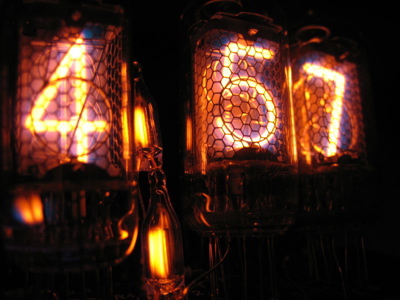
BTW: The picture above shows a Nixie tube clock. I ripped the picture shamelessly from flickr, there’s a photostream showing the creation of the clock. Cool project.
i cannot open the arduino-dcf77-clock-0.2.0.tar.bz file, after chang ing .bz to .gz winzip replys that it contains 0 files
Hi Erik,
I just downloaded the file to my linux box and it extracted smoothly:
$ tar xvjf arduino-dcf77-clock-0.2.0.tar.bz
Note that the archive is a BZip2 archive – I don’t have Windows around, maybe Winzip doesn’t understand this.
I uploaded a ZIP archive for you:
http://gonium.net/media/arduino-dcf77-clock-0.2.0.zip
Tell me if it works for you.
-Mathias
got the pde now, i still do not understand why i cannot the v2 file, the v1 file did work after removing the .bz extention.
thanks i will try v2 now
Hi Erik
what do you mean –> .bz extention.
And md! I have read the datasheet of Atmega168 and didn’t find timer2 (just find timer0/1)
Hi Mathias,
thanks for your very nice job.
I have an Arduino Duemilanove ATMEGA 328 and no idea on the diff with 168…
Pb whith TCCR2 at compile…
Thanks.
Hallo Mathias,
versuche mich auch gerade darin, Deine DCF77 Software auf meinen Arduino zu übertragen.
Leider habe auch ich einen Fehler beim Compilieren, weil TCCR2 nicht definiert ist.
Liegt das an V017 der Arduino Software?
Hi md
I just found your latest code on the project. but sadly I still can’t make it work with my diecimila >
In function ‘void DCF77Init()’:
error: ‘TCCR2′ was not declared in this scope
I use the latest enviroment 0017 – is this a problem?
Thanks a lot,
Stefan
Has anyone solved the TCCR2 problem yet? I’m using environment version 0017 too, and a duemilanove with an “ATMEGA328″.
I got it compiling properly by declaring the integer but also theres 2 others that need to be declared, so just add this near the top somewhere
int TIMSK;
int TCCR2;
int OCIE2;
So far with my reciever that i got today i have not got it working but its most likely my fault.
Rory
I have the same error and I am using a Freeduino V1.6 wtih the Conrad DCF77 and environment 015.
It’s the same form me!
error: ‘TCCR2′ was not declared in this scope
Are there any solutions until now?
I’m using Nano-Board and also Arduino-Software version 0017.
Hi Stefan
I have just the same problem with my Arduino Pro ATmega 328
In function ‘void DCF77Init()’:
error: ‘TCCR2′ was not declared in this scope
I use also the latest enviroment 0017
What have you done so that it runs the program?
Thanks a lot for your help,
Willy
Hallo Mathias,
Thanks for sharing the code, but I had nearly no chance to retrieve a clean signal from the conrad DCF77 receiver. Every 3 to 4 seconds the debug information shows several short signals before the 100ms and 200ms signals. I’ve modified the interrupthandler to ignore the jitter:
/**
* Interrupthandler for INT0 – called when the signal on Pin 2 changes.
*/
void int0handler() {
int length = millis() – previousFlankTime;
if (length < 10) {
// ignore jitter
return;
}
// check the value again – since it takes some time to
// activate the interrupt routine, we get a clear signal.
DCFSignalState = digitalRead(DCF77PIN);
}
and removed the DCFSignalState assignment in the main loop.
The problem concerning TCCR2 can be easily solved via the MsTimer2 Library. Changing the interrupt initialisation to:
/**
* Initialize the DCF77 routines: initialize the variables,
* configure the interrupt behaviour.
*/
void DCF77Init() {
previousSignalState=0;
previousFlankTime=0;
bufferPosition=0;
dcf_rx_buffer=0;
ss=mm=hh=day=mon=year=0;
#ifdef DCF_DEBUG
Serial.println("Initializing DCF77 routines");
Serial.print("Using DCF77 pin #");
Serial.println(DCF77PIN);
#endif
pinMode(BLINKPIN, OUTPUT);
pinMode(DCF77PIN, INPUT);
#ifdef DCF_DEBUG
Serial.println("Initializing timerinterrupt");
#endif
MsTimer2::set(1000, advanceClock); // 500ms period
#ifdef DCF_DEBUG
Serial.println("Initializing DCF77 signal listener interrupt");
#endif
attachInterrupt(0, int0handler, CHANGE);
}
removing the old interrupthandler and added the advanceClock function:
/**
* The interrupt routine for counting seconds – increment hh:mm:ss.
*/
void advanceClock() {
ss++;
if (ss==60) {
ss=0;
mm++;
if (mm==60) {
mm=0;
hh++;
if (hh==24)
hh=0;
}
}
}
The timer is started in "Parity check OK – updating time" branch via MsTimer2::start(). The sideeffect of placing the MsTimer2::start after a positive parity check is that the time is only printed after successful decoding of the DCF77 Data.
I'll mail you the complete sketch for integrating the changes in a version 0.0.3
Best regards
[...] mein DCF-77 Empfänger ab und zu Aussetzer zeigte, funktionierte der Code von http://gonium.net/md/2007/01/06/arduino-dcf77-v02-released/ leider nicht auf [...]